Many contractors underestimate what this involves until a failed inspection stops the project cold. Rework on a closed shaft wall is expensive, disruptive, and entirely avoidable with proper planning upfront.
This guide covers everything required to build a code-compliant 2-hour fire rated shaft wall correctly: the code triggers, material requirements, step-by-step installation sequence, common failure points, and what post-construction validation looks like before the AHJ signs off.
Key Takeaways
- 2-hour rating required per IBC 2024 Section 713.4 for shaft enclosures connecting four or more stories
- Follow a specific UL-listed design (such as W419); component substitutions without an equivalent listing void the rating
- Assembly uses J-track, shaftliner panels, CT/CH studs, and two layers of 5/8" Type X gypsum — installed from one side only
- Every penetration needs a listed firestop system with a matching UL System number — generic fire caulk is not compliant
- Document every stage and get AHJ sign-off before closing the wall
What Is a 2-Hour Fire Rated Shaft Wall and When Is It Required?
A shaft wall is a non-load-bearing, steel-framed gypsum board assembly designed to enclose vertical building elements — elevator shafts, stairwells, and mechanical chases. Unlike standard partitions built from both sides, shaft wall systems are engineered for single-side installation, making them the only practical option where interior shaft access doesn't exist during construction.
The Code Trigger
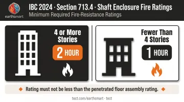
IBC 2024 Section 713.4 establishes the threshold:
- Four or more stories: 2-hour fire-resistance rating required
- Fewer than four stories: 1-hour rating required
- The rating must not be less than the fire-resistance rating of the penetrated floor assembly
IBC Chapter 7 further requires shaft enclosures to be constructed as fire barriers per Section 707, with all openings and penetrations protected under Chapter 7 requirements.
Impact Resistance Requirements
Fire rating compliance is only part of the picture — certain buildings carry a second, separate requirement. IBC Chapter 4 requires stairway and elevator shaft enclosures to include at least one layer of impact-resistant panels meeting Hard Body Impact Classification Level 3 under ASTM C1629.
Per National Gypsum's technical guidance, this applies to:
- High-rise buildings classified as Risk Category III or IV
- Buildings over 420 feet in height
Prerequisites and Code Requirements Before Construction Begins
Getting these prerequisites wrong is the most common cause of mid-project surprises. Address them before a single piece of track is cut.
Structural and Site Readiness
- Floor and ceiling deck must be complete and inspected — J-tracks anchor to structural members, and the substrate must accept the required fastener load
- Shaft dimensions on site must match the approved drawings; field deviations require a design review before framing begins
- Confirm that all MEP penetration locations are planned and documented — retrofitting firestopping into a closed shaft wall later means core drilling through fire-rated floor assemblies
Assembly Selection and Material Compliance
The contractor must identify the specific UL-listed design before ordering materials. National Gypsum's W419/U497 design is a commonly used 2-hour, one-side-access shaftwall assembly using 2½" 25-gauge C-T studs at 24" o.c. — but the point is not which assembly you use, it's that every component ordered must match the one selected.
No substitutions without a written confirmation that the substitute product appears in an equivalent listed assembly. Site-level swaps made without engineering review are the leading cause of rating voids.
High-Risk Zone Considerations
In California WUI areas — including Pacific Palisades rebuilds following the January 2025 fires — AHJs may require pre-submittal of UL assembly documentation and impose additional inspection hold points. Engage manufacturer technical support before design is finalized, so UL assembly documentation and inspection hold-point requirements are resolved before the plan checker asks for them.
Earth'smart powered by tect's Earth'smart™ approach builds manufacturer input into the project from concept forward, not reactively during permitting. Through the earth'smart powered by tectApp™ community of 70+ vetted building product manufacturers, the right assembly specifications and supporting documentation are in place before construction begins.
For homeowners overseeing a Pacific Palisades rebuild, that means no last-minute scramble at the inspection hold point — the documentation is already prepared.
Materials and Components Required
Every component must come from within the listed assembly — substituting or mixing products from outside it voids the fire rating. The components below fall into two categories: core items required in every 2-hour shaft wall assembly, and situational items triggered by specific building conditions.
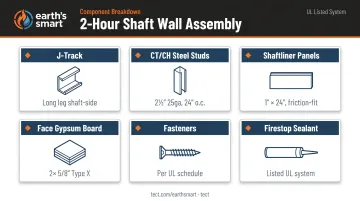
Core Assembly Components
| Component | Specification |
|---|---|
| J-track | Floor and ceiling, long leg facing shaft side |
| Steel studs | CT or CH profile, minimum 2½" depth, 25 gauge, 24" o.c. |
| Shaftliner panels | 1" thick × 24" wide, friction-fit into stud slots on shaft side |
| Face gypsum board | Two layers of 5/8" Type X fire-shield gypsum board, non-shaft face |
| Fasteners | Self-drilling bugle-head screws per the UL assembly schedule |
| Firestop sealant | Listed system with matching UL System number for each condition |
Situational Components
These components are required only under specific conditions, but when those conditions apply, they are mandatory:
- Deflection track at head-of-wall: Required where the assembly meets the deck above, to accommodate slab deflection; UL head-of-wall joint systems are tested to ASTM E1966 or UL 2079
- Resilient furring channels: Added when acoustic performance requirements apply
- Impact-resistant face board (ASTM C1629 Level 3): Required for Risk Category III/IV buildings and structures over 420 feet
How to Build a 2-Hour Fire Rated Shaft Wall: Step-by-Step
The installation sequence is not flexible. Track first, then liner panels and studs alternated, then face layers applied. Deviating from this order — installing face board before all liner panels and studs are seated, for example — creates deficiencies that require complete tear-out to fix.
Step 1: Attaching J-Tracks
- Fasten J-track to the floor and ceiling deck with the long leg oriented toward the shaft side
- Space fasteners at 24" o.c.
- Frame all duct openings and door openings with J-track to protect cut gypsum core edges and resist bending stress at openings
- Install a listed head-of-wall joint system at the ceiling track where the assembly meets the deck above
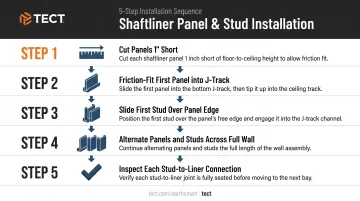
Step 2: Installing Shaftliner Panels and Studs
- Cut shaftliner panels 1" short of full wall height to allow for thermal movement
- Friction-fit the first panel into the long leg of the J-track
- Slide the first stud over the long edge of the panel so it locks into the floor and ceiling track
- Alternate shaftliner panels and studs across the full wall length
- Inspect each stud-to-liner connection for firm seating before moving to the next bay — loose fit or gaps here are a structural and fire rating problem
Step 3: Applying Face Layer Gypsum Board
For a 2-hour assembly, two layers of 5/8" Type X gypsum board go on the non-shaft (tenant) face:
- Base layer fastened with specified screws per the UL assembly schedule
- Face layer staggered both vertically and horizontally — joints must not align between layers
- Face layer joints offset a minimum of one stud bay from base layer joints
Fastener type and spacing are prescribed by the UL design. Using the wrong screw or exceeding the listed spacing causes fire assembly inspection failures, per the Gypsum Association's technical FAQ.
Step 4: Firestopping Penetrations and Head-of-Wall
Per IBC 2021 Chapter 7, penetrations in shaft enclosures must comply with Section 714. Through-penetration firestop systems must be tested to ASTM E814 or UL 1479, with an F rating not less than the required wall rating.
Every penetration type requires its own listed system:
- Metallic pipe, conduit, or tubing → UL penetration systems 1000–1999
- Nonmetallic pipe, conduit, or tubing → UL penetration systems 2000–2999
- Cable systems → separate UL penetration system categories
- Head-of-wall joint → UL joint system tested to ASTM E1966 or UL 2079
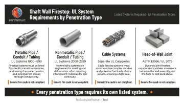
A single unsealed penetration voids the fire rating at that location — regardless of how correctly the rest of the wall was built. Generic fire caulk without a matching listed system does not constitute compliance.
Step 5: Post-Construction Checks Before Inspection
Before calling the AHJ for inspection, verify:
- All face layer joints are staggered — no continuous joint lines between base and face layers
- All fasteners are at specified spacing, not overdriven or missing
- No gypsum board is damaged, cracked, or improperly cut
- No gaps exist between panels at any joint
- All firestop is fully cured
- Every penetration has a documented, listed firestop system applied
Per the UL Firestop and Joint Application Guide, penetration inspections require witnessing 10% of each system type (or destructive verification of at least 2% per floor or 10,000 sq ft). Joint inspections require witnessing 5% of total linear feet, or destructive sampling once every 500 linear feet.
Maintain a photo log and retain material submittals for every component. That documentation lets you demonstrate compliance to the AHJ without opening the wall.
Common Shaft Wall Construction Problems and How to Fix Them
Wrong Materials Substituted Mid-Project
Problem: Shaftliner panels or face board from a different manufacturer are used when the specified product is unavailable.
Fix: Verify upfront that all materials are sourced from the same listed assembly before ordering. If a substitution becomes necessary, require written manufacturer confirmation that the substitute product appears in an equivalent UL assembly — written confirmation only, before installation proceeds.
Shaftliner Panel Gaps or Loose Stud Fit
Problem: Panels are not fully friction-fit into stud slots, leaving gaps or allowing panel movement under air pressure loads from elevator operation.
Likely causes: Panels cut too short, studs installed out of sequence, or incorrect stud gauge used.
Fix: Verify all panel cut dimensions against actual wall height before installation begins. Inspect every stud-to-liner connection before moving to the next bay. Replace any stud that doesn't engage the liner panel correctly — don't force it.
Unsealed or Incorrectly Sealed Penetrations
Problem: Electrical boxes, conduit sleeves, or pipe penetrations are left without listed firestop protection, or crews apply generic fire caulk without a matching UL System listing.
Likely cause: Firestopping is scheduled as a finish-trade closeout item and happens after the framing crew has moved on.
Fix: Address firestopping within the shaft wall scope from the start — not as a separate closeout item. That means:
- Including firestop requirements in the original framing scope
- Requiring product submittals for every firestop system before installation
- Documenting each penetration with a photo showing the listed system applied and fully cured
Pro Tips for Building a Code-Compliant 2-Hour Shaft Wall
Three practices separate compliant shaft wall projects from costly rework:
Map every MEP penetration before framing starts. Each duct, conduit, and pipe location should be confirmed and included in the firestop submittal before a single stud goes up. Retrofitting firestopping after the wall is closed is expensive and may require core drilling through rated floor assemblies.
Build your documentation as you go. Photograph each stage: J-track attachment, liner panel fit, stud engagement, face layer staggering, and each firestop application. Submit material data sheets and the UL assembly number to the AHJ before the inspection hold point — not the morning of inspection. For homeowners in a high-risk fire zone, earth'smart powered by tect structures this documentation process from day one, so UL assembly records and firestop submittals are ready before the inspector arrives.
Bring in a specialist for complex conditions. Shaft wall assembly in multi-story stairwells, elevator shafts, or any condition requiring ASTM C1629 impact resistance should be handled by a contractor with prior UL-listed shaft wall experience. If there's uncertainty about which assembly applies or whether a field condition falls within the tested design, contact the gypsum manufacturer's technical support line before proceeding.
Conclusion
A 2-hour fire rated shaft wall performs during a fire only if every component was installed exactly as tested and listed, every penetration was sealed with a listed firestop system, and the completed assembly was inspected and documented before close-in. There is no partial credit.
Getting it right upfront costs far less than getting it wrong. The three things that protect you:
- Correct assembly selection — match the tested listing to your actual framing, board type, and fastening schedule
- Proper firestopping — every penetration sealed with a listed system, installed as specified
- Complete documentation — inspection records and close-in sign-off before the wall is covered
A failed inspection, mandatory rework, or a system that doesn't perform when it matters costs multiples of what careful execution would have.
The listing tells you exactly what works. Follow it without shortcuts, document everything, and the assembly will do its job.
Frequently Asked Questions
What is a 2-hour fire-rated shaft wall?
A 2-hour fire-rated shaft wall is a non-load-bearing, steel-framed gypsum board assembly tested to resist fire and heat transmission for a minimum of two hours. It encloses elevator shafts, stairwells, and mechanical chases, and is specifically engineered for single-side installation where interior access isn't available.
What are the requirements for a 2-hour fire-rated shaft wall?
IBC 2024 Section 713.4 requires a 2-hour rated shaft enclosure in buildings where the shaft connects four or more stories. The assembly must follow a specific UL-listed design, governing stud type, liner panel, face board layers, and fastener requirements exactly. and all penetrations must be protected with listed firestop systems.
What is the typical composition of a 2-hour fire-rated shaft wall?
The standard assembly includes J-track at floor and ceiling, 1"-thick shaftliner panels friction-fit between CT or CH steel studs on the shaft side, and two layers of 5/8" Type X fire-shield gypsum board on the face side. All components must conform to the specific UL assembly number selected for the project.
Can a 2-hour fire-rated shaft wall be built from one side only?
Yes. Shaft wall systems are specifically engineered for single-side installation. The shaftliner-and-stud cavity system replaces conventional double-sided framing, making these assemblies the standard solution for elevator and stair shafts where interior access during construction is not practical.
What happens if a penetration in a shaft wall is not properly fire-stopped?
An unsealed penetration creates a direct path for fire and smoke to bypass the assembly, voiding the fire rating at that location regardless of how well the surrounding wall was built. Listed firestop products with matching UL System numbers are required for every penetration type; unlisted fire caulk does not satisfy this requirement.
Who should install a 2-hour fire-rated shaft wall?
Installation should be performed by licensed contractors with direct experience building UL-listed shaft wall assemblies, working with the gypsum and framing manufacturers specified in the assembly. Projects in high-risk or regulated areas, including WUI zone rebuilds, should include manufacturer technical support and AHJ pre-submittal review before construction begins.