This gap between "system installed" and "system validated" is where room integrity testing lives. In commercial data centers and server rooms, RIT is standard practice. In residential builds — including high-performance homes in wildfire-risk areas — it's frequently misunderstood, skipped entirely, or addressed far too late in the construction process.
This article covers what room integrity testing is, why the hold time standard exists, how the test is conducted, what causes failures, and how to design the enclosure correctly from the start.
Key Takeaways
- Room Integrity Testing (RIT) confirms whether a protected enclosure can hold suppressant gas at effective concentration for a minimum of 10 minutes — the threshold required for most clean agent systems.
- Testing uses a calibrated blower door to pressurize and depressurize the room, generating leakage data used to calculate Hold Time.
- Governing standards — NFPA 2001, ISO 14520-1, and FM Global DS 4-9 — require testing at commissioning and at least once per year.
- Most failures trace back to cable penetrations, door seals, porous materials, and unsealed HVAC pathways — rarely one large breach.
- Building airtightness into the design phase costs far less than fixing leakage after the suppression system is commissioned.
What Is Room Integrity Testing?
Room integrity testing — also called a fan test or door fan test — is the process of measuring how well a protected enclosure retains suppressant gas after a gaseous fire suppression system discharges. The result is expressed as a leakage rate and a calculated Hold Time: the predicted duration that the suppressant gas will remain at effective concentration inside the room.
The Hold Time Requirement
ISO 14520-1 requires a minimum Hold Time of at least 10 minutes for clean agent systems unless otherwise specified. NFPA 2001 frames this as 10 minutes or the time required for a trained response — the practical planning benchmark is 10 minutes for FM-200, IG-55, and IG-541 systems. CO2 systems require longer soak periods, with 20 minutes referenced for deep-seated fire hazards under NFPA 12.
That 10-minute window gives emergency services time to respond and prevents fire re-ignition before manual intervention. Understanding the minimum requirement is only half the picture — the other half is knowing which spaces must meet it.
Which Spaces Require RIT?
RIT applies to any room protected by a gaseous total-flooding suppression system. Typical applications include:
- High-value residential spaces where gaseous suppression is specified
- Archives, art storage, and collections rooms
- Server rooms and data centers
- Telecommunications and process control facilities
- Any enclosed area protecting irreplaceable or high-consequence contents
Neither ISO 14520-1 nor NFPA 2001 creates a separate residential category — the enclosure integrity requirements apply to any protected room regardless of building type.
Why Room Integrity Testing Matters
A well-designed, properly charged suppression system accomplishes nothing if the room can't hold the agent. SFPE identifies agent leakage through the lower portion of the enclosure as a recognized performance failure mode. As gas escapes, the agent-air interface descends below the level of the protected equipment, and suppression fails.
How the Agents Work — and Why Containment Matters
The two main agent categories suppress fire through different mechanisms:
- Chemical agents (FM-200/HFC-227ea) suppress by removing heat from the fire triangle and require direct, sustained contact with the fire source.
- Inert gas blends (IG-55, IG-541) suppress by reducing available oxygen below the level that supports combustion and require maintaining a depleted atmosphere throughout the room for the full hold period.
Both mechanisms depend entirely on the enclosure's ability to retain the agent. Neither works with a leaky room.
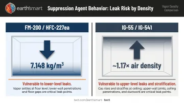
Agent Density Changes the Calculation
Different agents have different densities, and this matters for RIT. HFC-227ea has a vapor density of 7.148 kg/m³ at standard conditions. IG-55 (Argonite), by contrast, has a vapor density approximately 1.17 times that of air — far lighter. As SFPE notes, leakage through the lower portion of the enclosure is the primary pathway for heavier agents; lighter inert gas blends are more vulnerable to upper-level leaks and stratification.
A room that passes RIT for a denser agent may fail for a lighter one. Agent selection and enclosure design are interdependent decisions.
Compliance and Testing Cadence
FM Global DS 4-9 requires an enclosure integrity procedure (a door fan test) for all clean agent-protected occupancies, plus annual enclosure inspection including installed Pressure Relief Vents (PRVs). ISO 14520-1 and accessible NFPA 2001 materials align: testing at commissioning, re-evaluation at least every 12 months, and retesting any time changes affect enclosure leakage.
For insured properties, maintaining records of passing RIT results is not optional. It's the documentation that supports coverage.
Discharge Pressure and PRV Sizing
When suppressant gas discharges rapidly into a sealed or near-sealed enclosure, peak pressures of 240 to 1,200 Pa are possible, per SFPE. Peak pressures in that range can deform door frames, crack wall assemblies, and damage sensitive equipment. PRVs sized through the RIT process prevent structural damage, and they're tested at 125 Pa to verify their effective leakage area.
How Room Integrity Testing Works
The test uses the same blower door principle as commercial airtightness testing, but with specific methodology required by ISO 14520-1 and NFPA 2001. Both pressurization and depressurization runs are required. No temporary sealing of any element is permitted — results must reflect actual operating conditions.
Step 1 – Enclosure Preparation
Before testing, the engineer collects:
- Room volume (length × width × height)
- Type and quantity of suppressant agent installed
- Height of the highest protected equipment
- HVAC and damper configuration
All HVAC systems must remain in their normal operational state. Dampers should be set to auto-close as they would during an actual discharge — not manually closed for the test.
Step 2 – Blower Door Setup and Pressure Measurement
A calibrated fan is mounted in the room's doorway using an adaptable frame. ISO 14520-1 specifies:
- Fan pressure range: at least 25 Pa, preferably not exceeding 60 Pa
- Minimum five readings spaced across the range, down to 10 Pa
- Both pressurization and depressurization runs completed
This data characterizes the room's complete leakage profile across a range of pressure differentials.
Step 3 – Hold Time Calculation
Leakage data feeds into specialist software along with agent properties (including density) and room geometry. The software models how the suppressant gas will behave over time and calculates the predicted Hold Time.
The result is binary: Pass (Hold Time meets or exceeds the 10-minute minimum) or Fail.
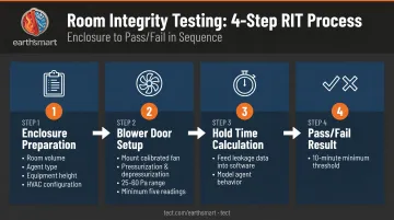
Step 4 – Peak Pressure and PRV Analysis
Engineers pressurize the enclosure to approximately 125 Pa to fully open the PRVs, which are then fixed open and tested to determine their effective leakage area. That data calculates the peak pressure spike during a real discharge and confirms that the PRVs provide adequate pressure relief, preventing structural damage to doors, walls, and equipment.
Hold time and peak pressure are separate calculations, but both results are required for a compliant report.
Common Failure Points and Remediation
Most RIT failures aren't caused by a single large breach. They result from an accumulation of small, often hidden leakage points — many introduced during post-installation work that wasn't coordinated with the suppression system.
Where Leaks Hide
Common failure locations identified by suppression contractors and engineering sources include:
- Cable tray and conduit penetrations through walls, floors, and ceiling voids — especially where cables were added after initial sealing
- Raised access floor perimeters — the junction between the raised floor system and the surrounding walls
- Door frames and bottom seals — worn seals or doors not rated for suppression enclosures
- Exposed or unpainted blockwork — porous construction materials that allow gas permeation
- HVAC duct penetrations that sit flush against slabs and are easily missed during installation
Remediation Approach
When a room fails RIT, the remediation sequence matters:
- Identify all leakage paths using the blower door data and a visual inspection.
- Seal with permanent, fire-rated methods — mastic around cable bundles, appropriate brush strips or seals on doors, penetration sealing compatible with the fire-rated assembly.
- Retest under identical conditions — no temporary sealing, same HVAC state.
Specialists should handle remediation. Incorrect sealing products frequently result in re-failure, and some improper fixes can compromise the fire-rated integrity of the assembly itself.
Catching leakage issues during construction — before commissioning — avoids the cost and schedule disruption of multiple re-test cycles. It also prevents the harder problem: discovering a compliance gap after the system is already active.

Building RIT Into Your Home From the Start
The commercial construction world treats enclosure airtightness as a design specification, not an afterthought. Server rooms and data centers have RIT requirements written into their construction documents from the concept phase. Residential projects with gaseous suppression systems rarely do.
The result is predictable: cable runs are laid without coordinated penetration sealing, HVAC is routed without accounting for the suppression boundary, and wall assemblies are chosen without anyone verifying they meet the enclosure's leakage requirements.
RIT then becomes a high-stakes audit of decisions that were already made.
The Airtightness Demand Is Real
Build Energy's reporting on fire suppression integrity testing includes a project example where the RIT requirement translated to an enclosure airtightness equivalent of 0.5 m³/h·m² — a performance level that rivals the most energy-efficient buildings. That's not a test-day problem. It's a construction-phase problem. Achieving it requires decisions made at design, not corrections applied after the fact.
Why Coordination Timing Matters
The suppression engineer needs to influence:
- Wall assembly selection (porous materials, masonry treatments)
- Cable routing and penetration strategies
- HVAC damper placement and auto-close logic
- PRV sizing and placement relative to structural elements
None of these decisions can be corrected cheaply once walls are built and systems are installed.
Getting ahead of those costs requires structural decisions and suppression engineering to happen in parallel — not sequentially. Earth'smart powered by tect's Earth'smart™ model is built around exactly that principle, whether through Path A Turnkey Delivery (a fully aligned architecture, engineering, and construction team from concept through completion) or Path B Advisory (owner-side coordination alongside an existing team).
Through the earth'smart powered by tectApp™ manufacturer community, the right system experts enter the project at design — when specifications are still open and coordination is still free.
When airtightness requirements shape the wall assembly choice, the HVAC layout, and the penetration plan from day one, RIT becomes confirmation of a well-executed design — not a first look at whether one was.
Frequently Asked Questions
How often should a fire suppression system be tested?
Per ISO 14520-1 and FM Global DS 4-9, enclosure integrity must be tested at commissioning and reviewed at least every 12 months. Retesting is also required any time modifications to the protected enclosure — new cable runs, equipment changes, renovations — could affect the room's leakage rate.
What is a fire integrity test?
A room integrity test uses a calibrated blower door to measure how well an enclosure retains suppressant gas at effective concentration for a defined Hold Time — typically a minimum of 10 minutes. The result predicts whether the room will hold the agent long enough for suppression to succeed.
What is the integrity test for FM-200?
FM-200 systems are tested using the standard RIT blower door methodology per NFPA 2001 and ISO 14520-1. Modeling software accounts for FM-200's specific density to calculate the predicted Hold Time. Because FM-200 is denser than inert gas agents, protected rooms are generally more tolerant of moderate leakage.
What is the minimum hold time for a room integrity test?
The minimum Hold Time for most clean agent gaseous suppression systems is 10 minutes, per ISO 14520-1 and NFPA 2001. CO2 systems require longer soak periods — 20 minutes is referenced for some deep-seated fire hazards under NFPA 12.
What are the most common causes of a failed room integrity test?
The most common failure causes include:
- Unsealed or poorly sealed cable and conduit penetrations
- Worn or improperly installed door seals
- Porous unfinished wall materials
- HVAC duct penetrations not sealed during installation
Most failures result from an accumulation of small leaks, not a single large breach.
Can changes to a room cause it to fail a test it previously passed?
Yes. Any modification to the protected enclosure — new cable runs, equipment installation, wall changes, HVAC work — can introduce new leakage paths and invalidate a previous passing result. This is why retesting is required after significant changes, and why maintaining records of all room modifications is part of responsible suppression system management.